
Frequency converter can transform AC mains through AC→DC→AC conversion and output pure sine wave power. It is mainly used in electronic devices with induction motor speed regulation. It is also an important device producing changeable voltage and frequency. For the adjustable frequency and voltage inverter, we call frequency converter. There is so much about the frequency converter, knowledge of the frequency converter circuits will be more numerous and complex. Here are several basic introductions about frequency converter circuit.
Frequency converter circuit
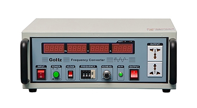
The frequency converter input single AC voltage and frequency, after an internal AC-DC, DC-AC converting, self-generating stable pure sine wave.
Whether for home or industry utilities, single phase or three phase AC power voltage, the voltage and frequency have a certain standard according to the provisions of its countries. In mainland China, single phase power supply is 220V, three phase power supply is 380V, frequency is 50Hz. Supply voltage and frequency may be different in other countries, such as single-phase 110V 60Hz, three phase 480v 60Hz in USA/Canada, and so on. Standard voltage and frequency of the AC power supply is called frequency alternating current
1. DC-AC converting circuit structure
PWM control circuit chip SG3524 is a voltage switching power supply integrated controller, with output current limiting, adjustable switching frequency, error amplifier, PWM comparator and shutdown circuitry. It can easily produce a square wave PWM peripheral circuitry required. When the pin 11 and the pin 14 parallel, the duty cycle of the output pulse from 0 to 95%, the pulse frequency is equal to 1/2 of the oscillator frequency. When the pin 10 (off stump) plus a high level, the output pulse can be realized on the blockade. If properly connected to an external circuit, it can be achieved under-voltage and over-current protection.
2. Under-voltage protection circuit
If the IR2110 bootstrap capacitor selection is not good, it will likely to cause frequency converter damaged or not working properly. Capacitance between VB and VS is the bootstrap capacitor. To be able to work properly, the bootstrap capacitor voltage should be 8.3V or more. Or you can use smaller capacitor, in order to improve the charging voltage, or provide 10~20V isolated power supply directly between VB and VS.
In order to reduce harmonic output, the DC/AC section generally applies bipolar modulation, which is high-frequency inverting bridge through complementary.

3. Over-current protection circuit
Over-current protection circuit monitors the output current situation, the default is 1.5A. Square wave inverter output current through the sample into the inverting input terminal of the operational amplifier. When the output current is greater than 1.5A, the output of op amp will jump to negative. After the RS flip-flop CD4011 composed of three tube making V1 base-level signal is low, three tube cut-off to the SD1-ended output of the IR2011, to achieve the purpose of protection.
A more important issue is to choose the debugging process encountered about IR2110 bootstrap capacitor. IR2110 on tube drivers are using the external power bootstrap capacitor, which makes the drive power of the large ones greatly reduced. But, it is also the choice of the bootstrap capacitor between the VB and VC requirements.
Summary
With the development of electronic technology, more and more advanced countries use frequency converter as a standard power supply, in order to provide the best electrical power supply environment. The frequency converter facilitates an objective assessment of the technical performance of electrical appliances. Learning the basics about the frequency converter circuits will benefit for your life.